Tasks of the inner receiver and receiver structure
As mentioned before in order for a digital transmission system to work, receiver and transmitter have to be synchronized. This involves the following tasks:
- Timing synchronization: Since it is unknown to the receiver, to which exact (absolute) time instant the symbol has been transmitted and how long the dispersion of the channel is, one essential task is to find the 'beginning' of a received OFDM symbol. Thus the time scales of transmitter and receiver are synchronized and the removal of the guard interval can be done with the required accuracy.
- Frequency synchronization: The signal is usually not transmitted in baseband but modulated with a radio carrier at a frequency assigned by the standard. Though this frequency is known to the receiver the tolerance of the RF components usually applied is so large that there will be a frequency-deviation. In many cases this deviation will be too large for a reliable data transmission. It therefore must be estimated and compensated at the receiver.
- Sampling-clock synchronization: The signal produced by the FFT will be converted into an analog signal assuming a certain span of time between two values. At the receiver the down converted RF signal is sampled in order to obtain a discrete time signal for further (digital) processing. The sampling times assumed in the receiver must match very accurately in order to avoid a degradation of the performance. A possible deviation between transmitter and receiver must again be estimated and compensated.
- Channel estimation: If a coherent modulation scheme is used (which must not be necessarily the case) according to equation (0.4) the channel transfer function must be estimated and compensated.
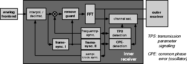
A receiver structure that allows to estimate and compensate all parameters required is depicted in figure 0.6.

Figure 0.6: Receiver structure for a DVB-T receiver
In addition to the elementary tasks found in single carrier receivers too for the receiver under consideration here two further tasks can be identified:
- TPS detection: So called TPS (transmission parameter signaling) data is provided in DVB-T to inform the receiver about the modulation and coding scheme used. This information is provided via selected subcarriers that are modulated in a robust differential BPSK.
- CPE detection (and correction): The common phase error (CPE) is a phenomena that results from imperfections of the oscillators used for modulation and demodulation. Instead of providing a stable frequency real oscillators tend to provide a frequency that is slowly changing in time. This change in time leads to an additional modulation of the OFDM signal which in some cases must be estimated and compensated. For the constellations used in DVB-T it can be shown that due to other reasons the quality of the oscillators must be so high that this effect can be neglected.
We will not go into detail as far as the implementation of the single components is concerned please refer to our literature. What proves to be the most critical component of the receiver is the channel estimation unit. We will therefore go a little more into detail.
Channel estimation for OFDM
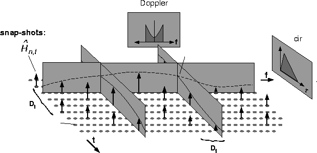
The method of channel estimation implied by the frame structure of DVB-T is channel estimation via interpolation. The basic principle is depicted in figure 0.7.

Figure 0.7: Principle of channel estimation via interpolation
Embedded into the OFDM data stream are training symbols (depicted as arrows) that can be used to obtain samples of the channel transfer function.

The values of the channel in between the samples can then be obtained via a interpolation procedure. Generally we have a two dimensional interpolation problem. Fortunately the problem can be separated into a interpolation in time and in frequency. The most critical task is the design of the interpolation filters used. Both interpolations must agree with the sampling theorem:
- The interpolation in time is bandlimited by the time-variant behavior of the channel. This is cause by a movement of the receiver and by uncompensated synchronization errors. The maximum allowable bandwidth of these disturbances is determined by the number of training symbols in one subcarrier.
- Due to the duality of time and frequency the interpolation in frequency is bandlimited by the length of the cir. The maximum allowable cir-length thus is not only determined by the length of the guard interval but also by the number of training symbols in one OFDM symbol. If we use fixed filters for implementation where the maximum dispersion to be assumed is given by the length of the guard interval this implies that for short guard intervals the channel can be estimated with a higher accuracy than with a larger guard interval.
For interpolation in frequency a interpolation filter optimized according to the Wiener filter theory is used. For interpolation in time a linear interpolation is sufficient.
Performance of the complete receiver
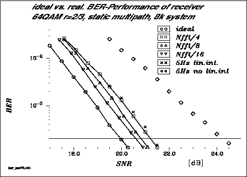
Figure 0.8 shows the results achievable with the channel-estimator described in the previous section. The application is a DVB-T receiver according to the European standard operating in 8k mode.

figure 0.8: Achievable performance for different channel estimators
As we can see the achievable system performance very much depends on the achievable quality of the channel estimator. Since it is higher for small cirs thus the performance of the receiver will be better. The loss with respect to the performance with ideal channel estimation ranges from about 0.5 dB for the smallest guard interval up to 1.6 dB for the largest guard interval. Also included are the results for a dynamic channel. Using linear interpolation in time will not further degrade the system. Alas if we try do without any interpolation in time the additional loss in performance is significant.